Troubleshooting Manual
Safety first!
When troubleshooting your Intergas Combi boiler please follow the following general fault finding procedure as most of the faults are caused by the three points below
- Verify electrical safety- test short circuit, earth continuity and resistance to earth tests. Check correct electrical polarity
- Verify electrical supply- verify if your appliance is connected to correct electrical supply- 230 V
- Verify gas supply- verify if your appliance is connected to the right gas supply and that it has been purged. Ensure the boiler has an inlet gas pressure of 20 mbar at the gas valve.
When suspecting water or gas leak turn off the electrical supply immediately, switch off the gas supply at the source- the meter, only then at the isolating valve, and ask the last step on the boiler. Call your customer support immediately and request Intergas boiler engineer as soon as possible. Contact your Gas Supplier immediately.
Warning! Use only qualified Intergas Boilers service engineers to work on gas boilers. Intergas accepts no responsibility for the bad appliance performance or flue arising from the 3rd party failure to comply with the user instructions or/and installation guides. Incorrect installation could invalidate your guarantee and may lead to prosecution. Remember to re-register the appliance if you buy used boiler that is still under warranty. If not re-registered your appliance will loose its warranty. Also if you use other than Intergas boiler installation specialist you will be responsible for installer conforming to the current legislation applicable for gas appliances and Standard Codes of Practice.
The Intergas Combi boilers are wall mounted, gas fired is a closed appliance and is a modulating high efficiency boiler. The appliance is designed to transfer heat to the water circuit in a central heating and domestic hot water installation. The combustion gas flue connection and the air supply is a prepared standard system built for a horizontal concentric flue system 60/100. The appliance can be connected to an expansion vessel or/and wall mounting jig. You can connect your boiler using the robo kit, not necessary connecting it to the wall.
If your appliance is to be installed in any room or compartment, it does not require any purpose made ventilation for combustion air. If sited in a room containing a bath or shower then particular reference is drawn to the current I.E.E. Wiring Regulations, local Building Regulations or any other local regulations currently in service. The Intergas Combi boilers are not suitable for external installation unless protected by a purpose made building such as a boiler house. The wall on which the boiler is mounted must be sufficiently strong to support the weight of the boiler. Intergas Combi boilers can be installed between two kitchen cabinets or in a kitchen cabinet itself. Ensure sufficient ventilation at top and bottom. When installed in a cabinet, ventilation openings of at least 50 cm2 must be created at the top and bottom of the appliance to ensure free flow of air.
Standard 230V ~ 50Hz electricity supply is required for all Intergas boilers. Never hang flammable items over the boiler, never block ventilation channels. The boiler does not require any special air vents for cooling purposes located in the room in which it is installed or when installed in a cupboard or compartment. The following clearances should be kept in order to provide enough cooling/ventilation: 300 mm below and 10 mm at each side, 200 mm above, 500 mm is required at the front but this may be performed also by opening a cupboard door. No flammable fluids and materials can be stored in 1 meter zone from your gas appliance.
The Intergas Compact Combi boilers are modulating high efficiency boilers. Modulating high efficiency means that the power is adjusted in line with the desired heat requirement. Newly designed aluminium heat exchanger is built from two separate copper circuits. Thanks to the separately constructed circuits for central heating and domestic hot water circuits can operate independently of each other. The hot water supply will always take priority over the central heating when demand for hot water is demonstrated. The two systems are not able to operate simultaneously. Each Intergas Combi boiler has an electronic boiler controller. The purpose of it is starting the operation sequence: gas valve will open, burner will ignite. Flame will be controlled for the whole demand period and will change based on the requested output. By setting the right parameters your appliance will be set to operate either on heating only or domestic hot water only, or domestic water and heating. Naturally it is possible to use domestic hot water circuit without connecting/ setting the central heating circuit.
Attention! The domestic hot water request will always draw its preference over the central heating request/ functionality. When a boiler is operating in winter mode your appliance will revert back to the heating mode, after a demand for domestic hot water was fulfilled.
Domestic hot water mode
Whenever hot water request appears (hot water tap is being opened) flow switch will close and the appliance will fire automatically. When this demand is finished pump will be stopped in order to allow all the heat to be utilized by domestic hot water system. There is an option of creating 1-15 min in answering for a demand that can be activated by setting the [o] parameter.
Central heating mode
Whenever a heating demand is requested – boiler is switched on , set for non summer operation, timer is set or/and thermostat is demanding the heat- the integral pump will be activated and the appliance will automatically fire. The hot water will be circulating around the central heating system. Whenever the central heating demand is finished or the desired temperature is reached, the appliance burner will shut down. The pump will still operate for the preset period of time releasing any excess heat from within the boiler’s heat-exchanger. After this is finished your appliance will revert to stand-by, waiting to respond to the next hot water or heating demand. During the heating period a call for hot water will take preference over heating.
Summer mode
When parameter q is set to a value unlike 0 (zero) it is possible to activate summer mode. During the summer mode a request for central heating is totally ignored. This mode does not affect the domestic hot water demand fulfillment. Summer mode can be activated by pressing the on/off button until the text, corresponding with the setting of parameter q appears in the display. Also choosing the on/off button again will end the summer mode and set the boiler in stand-by mode.
The Intergas Compact Combi HRE 36/30 and HRE 36/40 are suitable for supplying at least 13 liters of water per minute at the temperature of 35°C. The HRE 28/24 is designed for supplying at least 10.5 liters of water per minute and the HRE 24/18 is suppose to provide at least 8.5 liters of water per minute. The Intergas Compact Combi Compact as same as The Intergas Combi Compact give the possibility of appliance usage only for central heating or only for the hot water. The unused system doesn’t need to be connected, however boiler controller parameters need to be set properly. An electronic control unit that is is placed on the gas valve is responsibile for providing flame supervision, direct burner ignition with constant gas supply modulation.
The heat transfer to the boiler’s domestic hot water and the central heating circuits is achieved via gas to water heat exchanger within a combustion chamber that is hermetically sealed. A modulated speed fan blows the gas/air mixture into the combustion chamber and gives away the combustion products to outside air by flue system pipes. An integral pump is placed in the appliance s hydraulic circuit that circulate the water through the heat exchanger and further to the circuit of the central heating. During the domestic hot water demand the pump will stop operating to allow all the heat be directly transferred to the domestic hot water system without any heat losses on the way. Whenever normal water circulation is reduced or being interrupted best solution is an automatic system by-pass installation that should be placed as far away from the appliance as possible.
Frost protection
To prevent freezing the appliance is equipped with an internal frost protection. If the heat exchanger temperature falls too low, the pump the burner switches will work until the heat exchanger temperature will be sufficient. The symbol code 7 will appear onn the display in instances when the gas boiler frost protection is activated. If the installation (or a part of it) is in danger of freezing, an (external) frost thermostat must be fitted to the return line at the coldest location. This must be connected in accordance with the wiring diagram
Fault finding
All Intergas boilers are equipped with a LED display that will provide an error code, when a fault occurs. Fault message should be used for the proper communication with the boiler service team in order to provide fast and accurate solution or/and parts replacement
Table 1. General found finding for Combi Compact models based on error code message
| Error code | Fault | Solution/Reason |
| 0 | Sensor fault after self Verify | Replace S1 and/or S2 |
| 1 | Temperature too high | Air in installation. Pump not running. Unsufficient flow in installation, radiators closed, pump setting too low. Flow switch sticking. Replace S2. |
| 2 | S1 and S2 interchanged | Verify cable loom. Replace S1 or S2 |
| 4 | No flame signal | Gas tap closed. No or incorrect ignition gap. Gas supply pressure too low of failling. Gas valve or ignition unit not powered |
| 5 | Poor flame signal | Condensate drain blocked. Verify adjustment of gas valve |
| 6 | Flame detection fault | Replace ignition cable and spark plug cap. Replace ignition unit. Replace boiler controller |
| 8 | Incorrect fan speed | Fan catching on casing. Wiring between fan and casing. Verify wiring for poor wire contact. Replace fan |
| 10 |
Sensor fault S1; Flow switch does not disconnect
|
Verify wiring for break. Replace S1. Verify flow switch
|
| 11 | ||
| 12 | ||
| 13 | ||
| 14 | ||
| 20 |
Sensor fault S2
|
Verify wiring for break. Replace S2
|
| 21 | ||
| 22 | ||
| 23 | ||
| 24 | ||
| 29 |
Gas valve relay faulty
|
Replace boiler controller
|
| 30 |
Table 2 General found finding for Combi Compact models based on boiler funtionality
| Fault | Cause | Solution |
|
Burner does not ignite
|
Gas tap is closed. | Open gas tap |
| Air in the gas pipe | Remove air form gas pipe | |
| Gas supply pressure too low | Contact the gas supply company | |
| No ignition | Replace ignition electrode | |
| No spark. Ignition unit on gas valve faulty | Verify the cabling. Verify the spark plug cap. Replace the ignition unit | |
| Gas/air adjustment not correctly set | Verify adjustment. See gas/air adjustment | |
| Fan faulty | Verify the wiring. Verify the fuse , if necessary, replace the fan | |
| Fan dirty | Clean the fan | |
| Gas valve faulty | Replace the gas valve. Re-adjust the gas valve, see gas/air adjustment | |
|
Burner ignites noisily
|
Gas supply pressure too high | The house pressure switch may be faulty. Contact the gas company. |
| Incorrect ignition gap | Replace the ignition pin. Verify the ignition electrode gap | |
| Gas/air adjustment not correctly set | Verify the setting. See gas/air adjustment. | |
| Weak spark | Verify the ignition gap. Replace the ignition electrode. Replace the ignition unit on the gas valve. | |
|
Burner resonating
|
Gas supply pressure too low | The house pressure switch may be faulty. Contact the gas company |
| Recirculation of combustion gasses | Verify the gas flue an the air supply | |
| Gas/air adjustment not correctly set | Verify the setting, see gas/air adjustment | |
|
No central heating
|
Room thermostat weather-dependent adjustment not closed or faulty | Verify the wiring. Replace the thermostat. Replace the weather-dependant adjustment |
| No current (24 V) | Verify the wiring against the diagram. Verify the connector X4. Replace the faulty manager | |
| Pump not running | Verify the power supply. Verify connector X2. Replace faulty pump | |
| Burner not firing on CH: sensor S1 or S2 faulty | Replace sensor S1 or S2. See fault code | |
| Burner does not ignite | Go to burner does not ignite fault finding section | |
| The power is reduced | At high rpm the power has fallen by more than 5% | Verify appliance and flue system for fouling. Clean the appliance and flue system. |
|
Central heating does not reach temperature
|
Room thermostat setting incorrect | Verify the setting and if necessary adjust: Set to 0.1A |
| Temperature is too low | Increase the CH temperature. See Operating CH . Verify outside sensor for short circuiting. Rectify | |
| Pump not running correctly. Pump setting is too low | Increase pump setting, or replace the pump | |
| No circulation in the installation | Verify whether there is circulation: at least 2 or 3 radiators must be open | |
| The boiler power has not been correctly set for the installation | Adjust the power. See setting maximum CH power | |
| No heat transfer as a result of lime scale or fouling in the heat exchanger | De-scale or flush the heat exchanger on the CH side | |
|
No hot water
|
Flow switch not switching | DHW flow < 2.0 l/min. Replace the flow switch |
| No current at the flow switch (5V DC) | Verify the wiring according to the diagram | |
| Burner not firing on DHW: S3 faulty | Replace S3 | |
| Burner does not ignite | Go to burner does not ignite fault finding section | |
|
Hot water does not reach temperature
|
DHW flow to high | Adjust the inlet assembly |
| Temperature setting for water circuit too low | Set the hot water circuit, depending on the desired temperature | |
| No heat transfer as a result of lime scale or fouling in the heat exchanger DHW side | Descale or flush the exchanger DHW side |
Boiler resetting
Most of boiler faults can be solved by simple resetting the appliance. When a lock-out is indicated by means of a flashing LED above the key and a code on the main display, the appliance can be restarted by pressing the key. Attention! Check the nature of the fault on the basis of the fault codes in from the table 1 above and resolve the cause of the fault if possible before resetting the appliance.
PC interface
The boiler controller is equipped with an interface for a PC, it can be connected by Intergas Software Diagnostics and a right cable. This tool allows to control your appliance functionality thanks to which you can monitors the whole heating installation for extensive period of time.
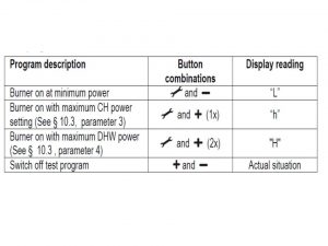
Test programs
You can test your boiler by using controller into the test mode. Whenever test mode is switched on test program will start at fixed fan speed, without the control functions being actuated. All necessary safety functions stay active while test program is running. The test program will end by itself after 10 min or if end option is chosen.
Test programs table
Parts replacement
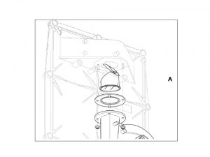
The original Intergas spare parts should always be used when replacing components. Failure to fit the sensors S1 and/or S2, or to fit them correctly can result in serious damage. The boiler is equipped with a non-return valve positioned above the fan, you need to make sure that the valve is being re-positioned in instances when fan is being replaced. Whenever parts need to be replaced you will need to start from removing the cover plate and front panel. It can be done by following the steps below:
1. Remove the front panel cover A by pulling it to the front as shown on the picture below
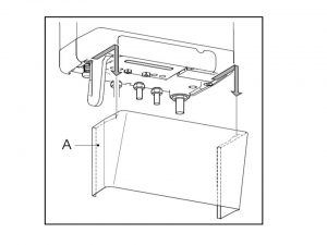
2. Unscrew the two screws located behind the appliance display window
3. Pull the bottom of the front panel forwards
4. Put the front panel aside for the time of repair
5. Re-assemble in reverse order
Annual service
The appliance and the installation should be checked annually for both safety and economy reasons. Whenever necessary the whole appliance or some of its parts need to be cleaned. Service should be performed by a Gas Safe Registered Intergas boiler expert. Following tools are recommended to use for performing an annual service: allen key 8 mm, cross head screwdriver and 30 mm fork spanner.
Disassembly
1. Isolate the boiler from the mains power and switch the boiler off. Close the gas tap
2. Gain general access by removing the front panel following the steps from parts replacement section above
3. Wait 15-25 min till the appliance cools down
4. Unscrew the coupling nut at the base of the flue pipe anti-clockwise as shown on the picture below
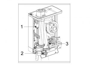
5. Slide the number 1 flue pipe upwards turning it anti-clockwise until the bottom of the pipe is above the condensate drain pan connection
6. Pull the bottom of the number 2 pipe forwards and remove the pipe number 3 downwards turning it anti-clockwise
7. Lift the condensate drain pan on the left-hand side from the connection to the number 4 condensate trap and turn it to the right with the condensate trap connection over the edge of the base tray number 5 as shown on the picture below
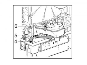
8. Push the back of the condensate drain pan downward from the connection to the number 6- heat exchanger and remove it from the appliance
9. Remove the connector from the fan and the ignition unit from the gas valve
10. Coupling under the gas valve should be now unscrewed
11. Unscrew the shoulder bolts from the front cover and remove this complete with gas valve and fan to the front. Make sure that the insulation plate, burner, gas supply, gas valve, fan and gas supply do not get damaged
Attention! When the appliance is connected to a wall mounting jig with built-in expansion vessel a regular inspection of the expansion vessel pressure is advisable. Access to re-pressurise the expansion vessel is at the rear back of the vessel.
Cleaning the appliance
Annual cleaning to the parts shown on the picture should be done by following the steps below:
1. Clean the heat exchanger from top to bottom with a plastic brush or compressed air
2. Clean the underside of the heat exchanger
3. Clean the condensate drain pan with water
4. Clean the condensate trap with water
Assembly
Warning! When fitting verify the condition of hardening, tears, various seals, hairline tears and/or discoloration. Wherever needed replace with a new one. All seals need to be correctly positioned. To correctly assemble the appliance follow the steps below
1. Verify presence of the small ceramic grease layer on the contact surface between the heat exchanger and the front plate
2. Mount the front cover to the heat exchanger and attach this with the socket screws with spring washers
3. Tighten the sockets crosswise. The torque required for the front plate bolts is 10 – 12 Nm.
4. Verify that the silicon gasket was placed correctly
5. Under the gas valve mount gas coupling
6. Check the sealing ring for damage and replace if necessary
7. Fit the connectors on the gas valve and the fan
8. Open the gas tap and check the gas couplings located under the gas valve and on gas couplings located on the mounting bracket- check if there are no leaks
9. Verify the central heating and the water pipes for leaks
10. Electrical supply now can be turned on
11. Put the appliance into operation
12. Verify the front cover and the connection of the fan to the front cover for leaks
13. Verify combustion functionality
14. Fit the cover and screw it left and right at the bottom of the appliance
15. Check the hot water supply and the heating system
Boiler start up
Before boiler start up your gas appliance should be checked and properly connected to: gas, water, and electricity. We recommend that your appliance is always checked by an authorized person. Your gas boiler should be started by following the points below:
- fill in and bled the domestic hot water system and the central heating system. Never switch the appliance on if the appliance, the CH system and the DHW system have not been completely filled and bled
- fill in the water pressure in the central heating system to the value somewhere between 1 and 2 bar (exact value will be displayed on the temperature display)
- set the room thermostat for the temperature below room’s temperature
- open gas tap
- switch on the boiler by using the on/off key in the display (The LED lights up, and the service display goes out)
- set the clock and the switch moments per your preferences and as described in separate sections of this troubleshooting manual
- set the room thermostat higher than the actual room temperature
Boiler shutting down
In instances when you will not be using your boiler for a longer periods of time- weeks or moths you should properly switch it off. Remember to drain the appliance and the installation if mains power has been interrupted and there is a possibility of freezing. To correctly shut down the boiler follow the steps below:
- drain the appliance at the drain tap
- drain the installation at the lowest point
- close the main cock for the water supply to the domestic hot water section
- Drain the appliance by removing the domestic hot water couplings located below the boiler
Attention! In order to avoid freezing of the condensate drain pipe the appliance must be installed in a frost-free area. If the temperature of the heat exchanger becomes too low, the burner switches on until the temperature of the heat exchanger is sufficient. If there is a possibility of the installation (or part of it) freezing, an (external) frost thermostat must be installed at the coldest point of the return pipe.
Filling and bleeding the boiler and the system
To correctly feed and bleed the boiler and the system first switch the appliance off with the key. Perform filling and bleeding. Do not switch the appliance on again until after filling and bleeding is completed.
Condensate disposal
The appliance is provided with a 25 mm flexible pipe from its condensate trap. The flexible tube (from the condense trap) should be connected to the drain via an open-connection.
Attention! Before powering up the boiler fill in the condensate trap with necessary water. Place it on the appliance. Not placing or filling up the condensate trap may cause flue gases to come into the installation room and can lead to dangerous situations! The front cover needs to be removed entirely if you want to properly place the condensate trap.
The condensate discharge system, pipework and fittings must be made of plastic. No other materials may be used.
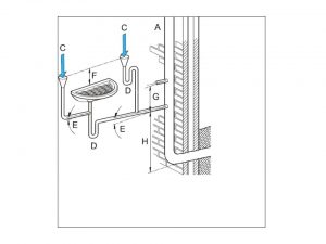
The discharge duct must have a gradient of 5 – 20 mm/m throughout its length. Condensate discharge via the gutter is not allowed given the risk of frost and the possible damage to materials
A. Internal stack pipe (see diagram)
B. Gully
C. Condensate discharge from boiler
D. Waste trap that can be serviced
E. 5 – 20 mm/meter
F. more than 100 mm
G. more than 110 mm
H. more than 450 mm
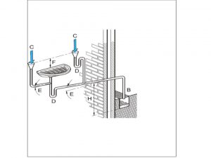
In instances where condensate drainage pipe is an external solution following setting should be used for frost prevention:
– the internal pipe lenght should be as long as possibe, and exernal part as short as possible, the diameter of condensate pipe should minimum 3omm (inner pipe dimention) before it goes though the wall
– the external pipe should be kept as littel as possible, the most vertical route should be chosen to the discharge point, and no horizontal pipes should be used
– the external pipe should always be insulated with the proper waterproof insultaion
– use elbows and fittings only where this is the only possible solution of pipe fitting
Clock function
The boiler incorporates an integrated clock, which allows the setting of central heating periods. Your appliance control panel has a LED display, which will show operation mode and error fault once it occurs. Your appliance is also equipped with a digital clock. Digital clock provides programming in 4 points of time. The purpose of 4 points programming is to switch from central heating off to on and vice versa. During the period when clock is set your appliance will respond on central heating request coming form the room thermostat. During the period when clock is set to off your appliance won’t react to central heating request. On the top of it following modes can be selected special modes can be chosen:
- t-on temporary on- your appliance will react to every central heating request coming from from the room thermostat until the next switch moment
- c-on continuous on- your applaince will react to every central heating request from the room thermostat without any time limit
- OFF- your appliance won’t react to every central heating request from the room thermostat
Setting the clock
To set the clock follow the steps below:
- Press the button for less than 1 second and repeat this untill ‘’24hr clock’’ appears
- For adjusting the clock to the correct time press the [+] or [-] button. Attention! Holding the button for more than 1 second will make the clock run fast
Setting the timer function
To set the timer function follow the steps below:
1. On pressing the button for more than 2 seconds the clock display will flash
2. The time for each on/off shows in the clock display and the service display shows which on 1 and 3 OR off 2 and 4 time is being set
3. Pressing the button again will change between the different on/off switching periods.
Values of the pre-set times as follows:
Display : [06:00] and [1] Start first period CH on. [09:00] and [2] End first period CH off. [16:00] and [3] Start second period CH on.[22:00] and [4] End second period CH off.
4. By pressing the button the new times will be stored in the boiler controller. In the service display [P] appears.
5. When the clock is in period [1] or [3] (CH ON) the clock symbol LED is on.
6. When the clock is in period [2] or [4] (CH not active) the LED is on.
7. By pressing the button over 5 seconds the default setting for the switch moments will be restored.
8. In the service display “F-set” appears.
9. By pressing the button the boiler controller will return to the normal situation without storing any changes.
Room temperature control
Room temperature can be controlled by the use of an external room thermostat and thermostatic radiator valves.
Attention! Connection of of the room thermostat is dependant on the operating voltage of the thermostat.